DL/T645-2007 and MODBUS Protocol Parsing and Debugging for Smart Meters
Recently, in the research process of electricity load forecasting, real-time electricity load data needs to be collected, which requires a smart meter to collect data. During the debugging of this smart meter, messages need to be sent and parsed, hence this record.
Introduction to DL/T645-2007 Protocol
The DLT645 protocol is a domestic electric meter remote transmission protocol, similar to the Modbus protocol, using a request-response interaction model. The collector and the meter communicate in a question-and-answer manner. The electrical layer can be the classic RS485 wired communication or non-contact infrared wireless communication. DLT645 is a communication standard in the domestic power industry, and meters from both the State Grid and the South Grid generally support it. To date, there are two versions: the DL/T645-1997 protocol and the DL/T645-2007 protocol, hereinafter referred to as the 97 protocol and the 07 protocol. Both have similar frame structures. Newly manufactured meters all support the 07 protocol, and to ensure backward compatibility, meters that support the 07 protocol also support the 97 protocol, allowing communication with both protocols.
DL/T645-2007 Protocol Format
Each data consists of seven fields: frame start character, slave address field, control code, data field length, data field, frame information longitudinal check code, and frame end character. Each part is composed of several bytes.
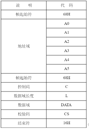
Generally, there are 0 to 4 FE bytes before the start character. When the master station sends a command, it can directly send 4 FE bytes, but the slave station’s response may or may not include FE bytes.
68 AA AA AA AA AA AA 68 11 04 33 33 34 33 AE 16

Frame Start Character: 68
Address Field: AA AA AA AA AA AA
Frame Start Character: 68
Control Code: 11
Data Field Length: 04
Data Field: 33 33 34 33
Check Code: AE
End Character: 16
Address Field
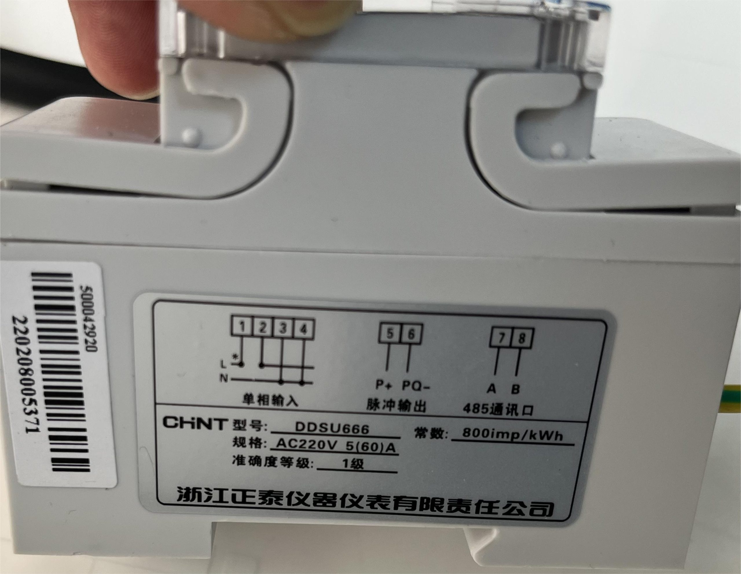
The address field consists of 6 bytes, with the low byte transmitted first and the high byte last. Taking the smart meter shown below as an example, the serial number is 220208005371, and the meter address defined by the manufacturer is 71 53 00 08 02 22.
Control Code
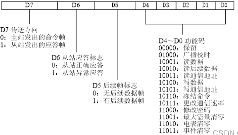
This part is similar to the Modbus function code but is more complex and carries more information. The program uses this control code C to determine subsequent operations.
-
For the master station read data function code, according to the above figure, D7~D0 in binary is 0001 0001, converted to hexadecimal: 11
-
For the master station write data function code, according to the above figure, D7~D0 in binary is 0001 0100, converted to hexadecimal: 14
-
For the slave station read data function code, according to the above figure, D7~D0 in binary is 1001 0001, converted to hexadecimal: 91
Data Field Length
04, indicating that it contains 4 bytes of data.
Data Field
The data field includes data identifiers, passwords, operator codes, data, frame sequence numbers, etc., and its structure changes with the function of the control code.
The data field is transmitted with the low byte first and the high byte last. During transmission, the sender processes each byte by adding 33H, and the receiver processes each byte by subtracting 33H.
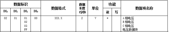
Taking reading voltage as an example:
Send 68 71 53 00 08 02 22 68 11 04 33 32 34 35 A3 16
    Sent Data Field: 33 32 34 35, after subtracting 33H processing: 00 FF 01 02, low byte first and high byte last, corresponding to the voltage data block in the protocol standard document.

Reply 68 71 53 00 08 02 22 68 91 0A 33 32 34 35 8C 55 33 33 33 33 D6 16
    Reply Data Field: 33 32 34 35 8C 55 33 33 33 33
    Among them, 33 32 34 35 is the data identifier, processed to 02 01 FF 00, i.e., the voltage data block
    8C 55 33 33 33 33 data after subtracting 33H processing: 59 22 00 00 00 00, converted to decimal: 22818, moving the decimal point two places forward to get 228.18V
Common data identifiers include:
Voltage Data: 0201FF00
Current Data: 0202FF00
Instantaneous Apparent Power: 0205FF00
Instantaneous Total Active Power: 0203FF00
Instantaneous Total Reactive Power: 0204FF00
Instantaneous Total Apparent Power: 0205FF00
Power Factor Data Block: 0206FF00
Neutral Current: 02800001
Forward Active Total Energy: 0001FF00
Reverse Active Total Energy: 0002FF00
Combined Reactive Energy 1: 0003FF00
Combined Reactive Energy 2: 0004FF00
Forward Active Total Maximum Demand and Occurrence Time: 01010000
Operating Status Word: 040005FF
Grid Frequency: 02800002
Current Active Demand: 02800004
Check Code
The sum of all bytes from the first frame start character to the byte before the check code, modulo 256, i.e., the arithmetic sum of the bytes in binary, excluding overflow values exceeding 256.
Introduction to Modbus Protocol
The Modbus protocol currently exists in three versions: Modbus RTU, Modbus ASCII, and Modbus TCP.
- Modbus RTU protocol is a compact protocol that uses binary representation of data with a cyclic redundancy check for the checksum.
- Modbus ASCII protocol is a verbose, human-readable representation with a longitudinal redundancy check for the checksum.
- Modbus TCP protocol, in this mode, checksum calculation is not required due to TCP’s data integrity assurance.
Most Modbus devices, such as liquid level meters, flow meters, smart meters, etc., use serial communication and adopt Modbus RTU and Modbus ASCII protocols. PLC devices generally use TCP/UDP connections and adopt the Modbus TCP protocol. Due to device limitations and the need for serial communication, Modbus RTU over TCP/UDP communication can also be used, i.e., using TCP/UDP connections but employing the Modbus RTU protocol.
Modbus RTU
Modbus RTU is the commonly used protocol for sensor-type devices and ordinary smart meters, and it is essential to understand it clearly.
Request: 01 03 00 00 00 02 C4 0B
01: Device Address, the device address is 1
03: Function Code, currently 03 for read request
00 00: Register Start Address, read from register 00 00
00 02: Read Register Length, read 2 registers, corresponding to 4 bytes of data
C4 0B: CRC Checksum
Reply: 01 03 04 00 0C 00 02 BB F1
01: Device Address, the device address is 1
03: Function Code, currently 03 for read reply
04: Data Length, contains 4 bytes of data
00 0C: Register 1 Value
00 02: Register 2 Value
BB F1: CRC Checksum
Modbus ASCII
The same command expressed in both Modbus RTU and Modbus ASCII, although the command length differs significantly (ASCII is twice as long as RTU), conveys the same meaning, so it is not recommended for use.
Request: 3A 30 31 30 33 30 30 30 30 30 30 30 32 46 41 0D 0A
3A: Start Character
30 31: Device Address
30 33: Function Code
30 30 30 30: Register Start Address
30 30 30 32: Read Register Length
46 41: LRC Checksum
0D 0A: End Characters
Reply: 3A 30 31 30 33 30 34 30 30 30 43 30 30 30 32 45 41 0D 0A
3A: Start Character
30 31: Device Address
30 33: Function Code
30 34: Data Length
30 30 30 43: Register 1 Value
30 30 30 32: Register 2 Value
45 41: LRC Checksum
0D 0A: End Characters
Modbus TCP
Since TCP ensures data accuracy, the checksum is omitted in the protocol.
Request: 00 00 00 00 00 06 01 03 00 00 00 02
00 00: Transaction Identifier, indicating the communication sequence number, matching the reply, used to determine if the request and response match
00 00: Protocol Identifier
00 06: Remaining Length
01: Device Address
03: Function Code
00 00: Register Start Address
00 02: Read Register Length
Reply: 00 00 00 00 00 07 01 03 04 00 0C 00 02
00 00: Transaction Identifier
00 00: Protocol Identifier
00 07: Remaining Length
01: Device Address
03: Function Code
04: Data Length
00 0C: Register 1 Value
00 02: Register 2 Value
Smart Meter Debugging
Smart Meter Introduction
This time, we use the DDSU666.001 single-phase electronic energy meter (rail-mounted) from Zhejiang Chint Instrument & Meter Co., Ltd.
The DDSU666 single-phase electronic energy meter (rail-mounted) (hereinafter referred to as “the meter”) is designed for power monitoring and energy metering needs in power systems, communication industries, construction industries, etc. It is a new generation of smart meters, integrating measurement and communication, mainly used for measuring and displaying electrical parameters such as voltage, current, power, frequency, power factor, and active energy in electrical circuits. It can be networked with external devices via the RS485 communication interface; it adopts a quasi-DIN35mm rail-mounted installation with a modular design, featuring small size, easy installation, and easy networking. It is widely used in electricity monitoring and metering in industrial and mining enterprises, hotels, schools, and large public buildings.
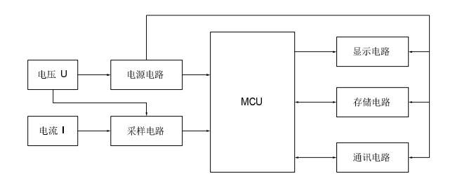
Working Principle:
The meter converts voltage and current signals into signals recognizable by the MCU through a sampling circuit. The MCU calculates and converts these signals into electrical parameters such as energy, power, and power factor, and displays them to the user through a display circuit. Additionally, the data is saved to the storage circuit. The meter can also communicate with other communication devices that comply with its interface and protocol through the communication circuit. The block diagram of the meter’s working principle is shown below:
Communication Function:
The meter uses RS485 communication, with baud rates selectable at 1200, 2400bps, 4800bps, and 9600bps. Up to 32 meters can be connected simultaneously on the same communication line, and each meter can be set with its communication address. The communication connection should use shielded twisted pair cables with copper mesh, with a diameter of not less than 0.5mm². When wiring, the communication lines should be kept away from strong power cables or other strong electric field environments. The maximum transmission distance is 1200m. A typical network connection method is shown below, and users can choose other appropriate connection methods based on their specific situations.
Connection Method:
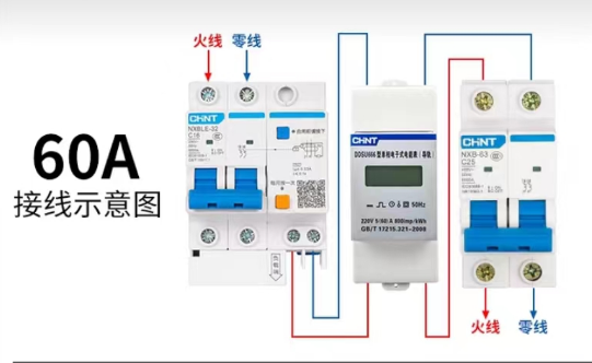
Smart Meter Local Debugging
Using a USB to 485 converter tool to connect the smart meter, with the USB connected to the computer, use a serial port debugging assistant to send and receive messages. Once local debugging is successful, the smart meter can be added to the load and connected to the smart gateway for deployment.
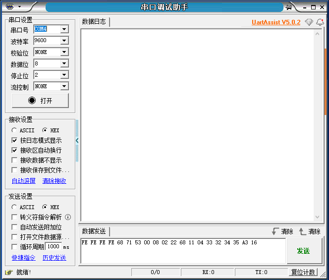
645 Message
Query Device Address
Send 68 AA AA AA AA AA AA 68 11 04 33 33 34 33 AE 16
Reply FE FE FE FE 68 71 53 00 08 02 22 68 91 08 33 33 34 33 33 33 33 33 F2 16

Query Voltage
Send FE FE FE FE 68 71 53 00 08 02 22 68 11 04 33 32 34 35 A3 16
Reply FE FE FE FE 68 71 53 00 08 02 22 68 91 0A 33 32 34 35 8C 55 33 33 33 33 D6 16

Query Active Power
Send FE FE FE FE 68 71 53 00 08 02 22 68 11 04 33 33 34 33 A2 16
Reply FE FE FE FE 68 71 53 00 08 02 22 68 91 08 33 33 34 33 33 33 33 33 F2 16

Query Current
Send FE FE FE FE 68 71 53 00 08 02 22 68 11 04 33 32 35 35 A4 16
Reply FE FE FE FE 68 71 53 00 08 02 22 68 91 0D 33 32 35 35 33 33 33 33 33 33 33 33 33 F8 16

Switch to Modbus Protocol
Send FE FE FE FE 68 71 53 00 08 02 22 68 14 0E 33 33 35 3D 35 33 33 33 33 33 BA 16

Modbus Message
Query Voltage
Send 47 03 20 00 00 02 C1 6D
Reply 47 03 04 43 62 CC CD FD 38

Query Current
Send 47 03 20 02 00 02 60 AD
Reply 47 03 04 00 00 00 00 DD F7

Query Device Address
Send 47 03 00 06 00 01 6A AD
Reply 47 03 02 00 47 71 B9

Switch to 645 Protocol
Send 47 10 00 05 00 01 02 00 01 7D A6
Reply 47 10 00 05 00 01 1F 6E
Smart Meter and Gateway Debugging
The edge computing gateway can periodically send Modbus messages to collect electricity data and transmit the data to the backend server for processing through protocols such as MQTT, HTTP, TCP, etc., for applications like load forecasting.

The smart gateway uses the BMG700 edge computing gateway from BaiMa Technology. The product features a high-performance industrial-grade high-end processor, equipped with rich data collection, control, and transmission interfaces, integrating 2G/3G/4G/NBIoT/GPS/WiFi/有线等多种 communication methods, with powerful local storage and expandable storage functions. It provides customers with integrated functions such as data collection, local storage, multi-protocol conversion, smart gateway, security gateway,全网通/4G wireless communication, data processing and forwarding, VPN virtual private network, WiFi coverage, local and remote control. The product uses the Linux operating system, integrating Python and C language development environments, supporting MQTT, HPPT, TCP, UDP, and other communication protocols, capable of local data collection and simple data processing.
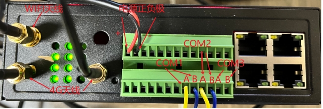
According to the wiring requirements of the industrial gateway and the smart meter, connect the A, B terminals of the smart meter’s 485 interface to the COM port of the industrial gateway. Connect the other power lines, 4G antennas, and WiFi antennas as per the industrial gateway’s manual. Finally, connect the industrial gateway to the computer via a network cable and enter the gateway’s configuration interface. Configure the collection frequency, basic serial port parameters, Modbus rules, reporting server, and reporting protocol.
Collection Frequency

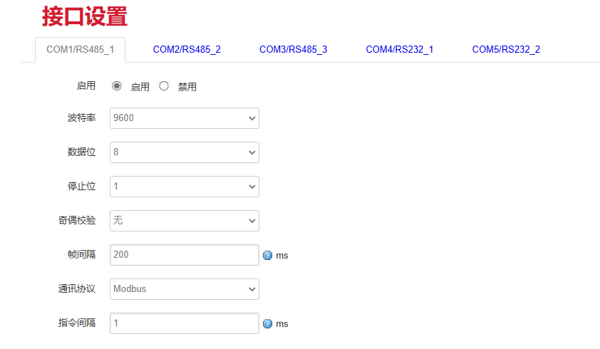
Serial Port Basic Parameters
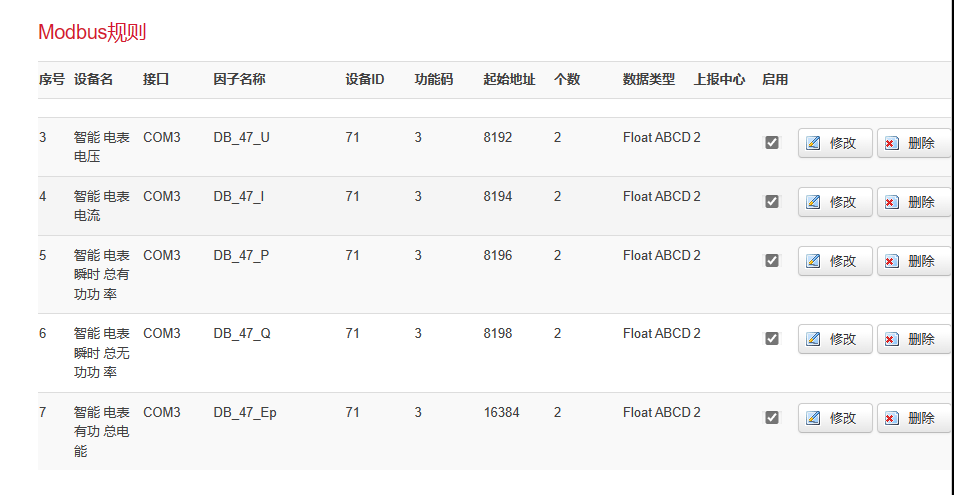
Modbus Rules
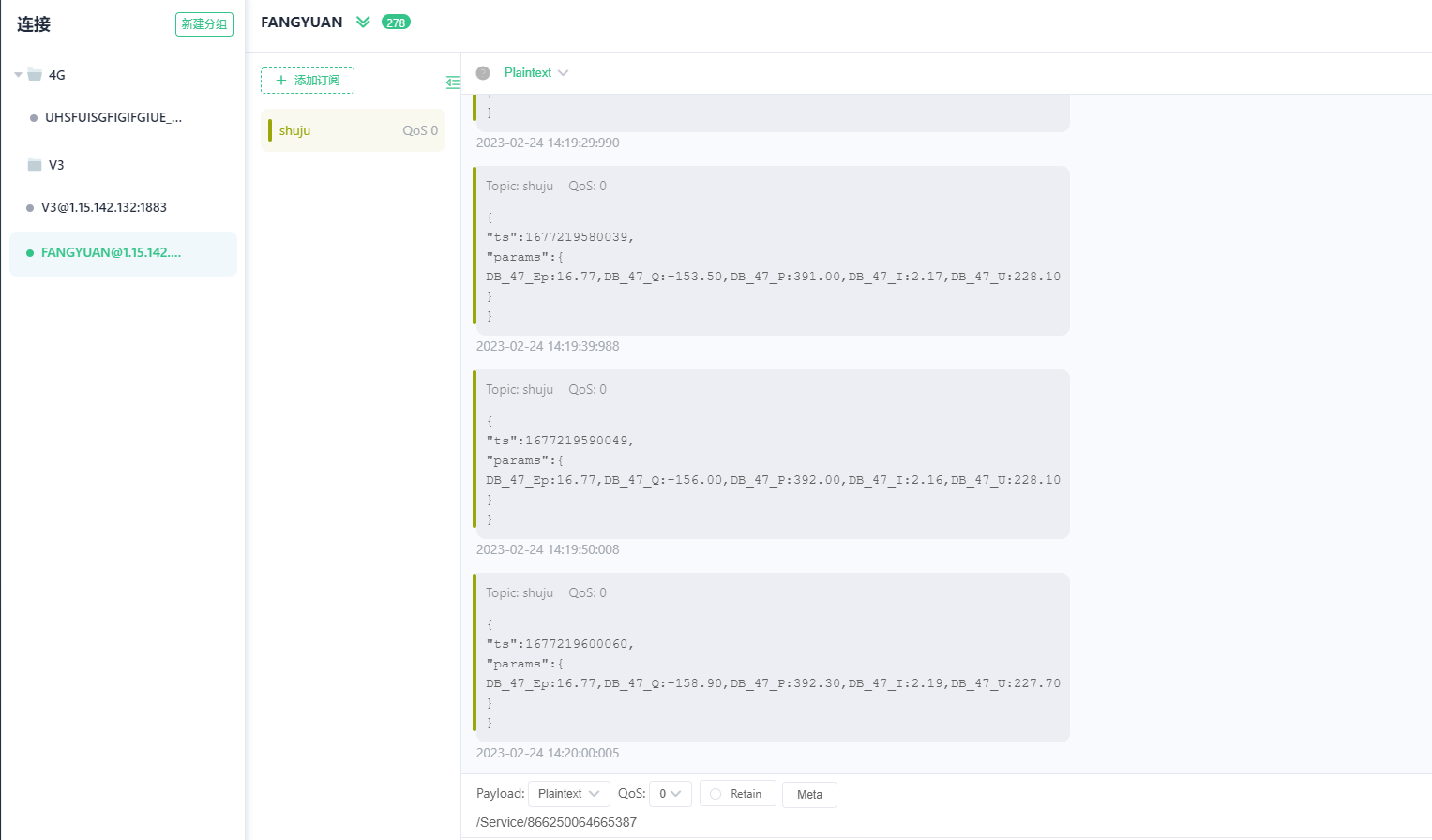
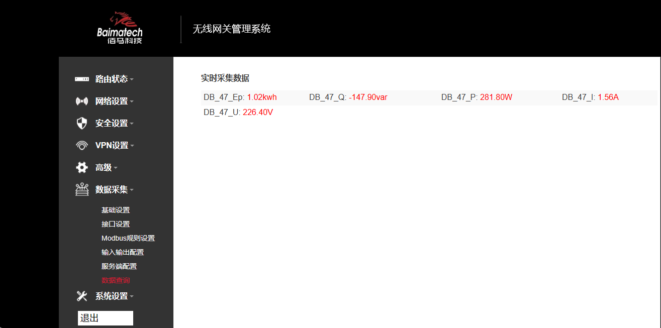
Collection Results
Reporting Results